ESP32 Series Comparison and Selection Guide#
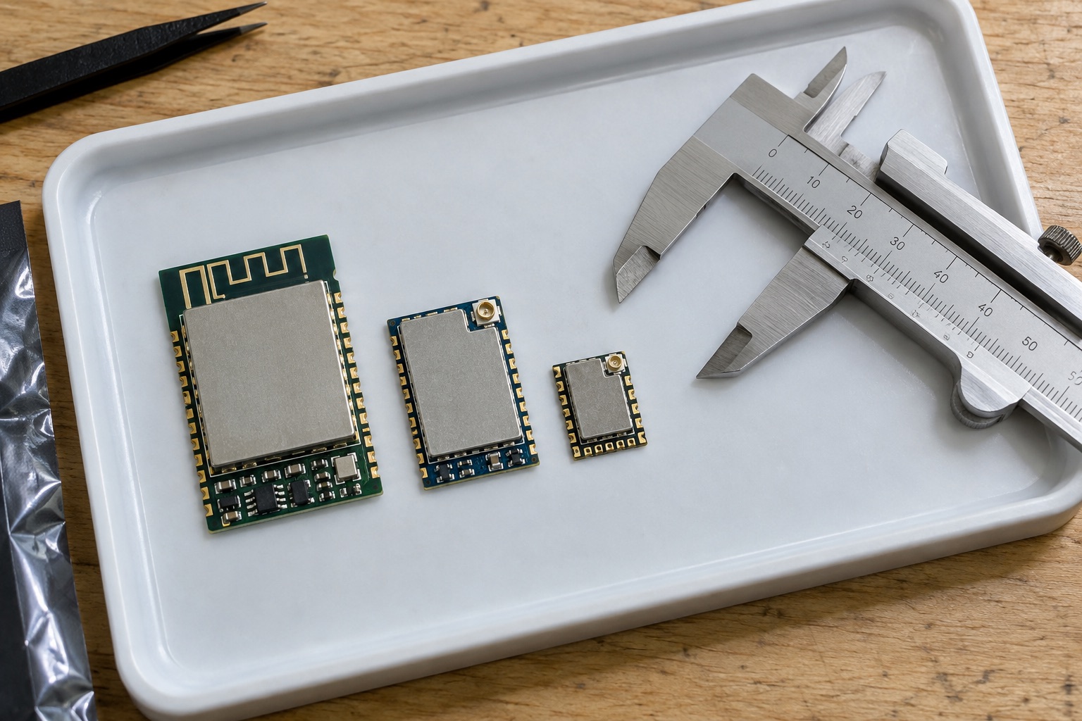
AI-generated illustration of module selection; hardware shown is not a verified comparison sample.
Quick Answer#
Choose an ESP32 family by required connectivity first, application resources second, and module constraints third. ESP32-S3 is worth evaluating for compact interfaces and signal processing; C3 for relatively small Wi-Fi applications; C6 when Wi-Fi and IEEE 802.15.4 are relevant; and H2 when a Bluetooth LE or mesh endpoint does not need native Wi-Fi. These are starting points, not universal winners.
This comparison deliberately covers a selected shortlist. Espressif’s portfolio extends beyond these chips, so consult the official selector for additional candidates. The method below helps eliminate unsuitable architectures before investing in board layout. It does not assign numerical performance scores unsupported by a common benchmark.
A Connectivity-First Comparison#
| Family | Native Radio Direction | First Question To Ask |
|---|---|---|
| Original ESP32 | 2.4 GHz Wi-Fi, Bluetooth Classic and LE | Is a required Classic profile the deciding factor? |
| ESP32-S3 | 2.4 GHz Wi-Fi, Bluetooth LE | Does the UI or signal workload need extra resources? |
| ESP32-C3 | 2.4 GHz Wi-Fi, Bluetooth LE | Can the complete application fit comfortably? |
| ESP32-C6 | 2.4 GHz Wi-Fi 6, LE, IEEE 802.15.4 | Which network role will actually ship? |
| ESP32-H2 | Bluetooth LE and IEEE 802.15.4 | Is the installation prepared for mesh networking? |
| ESP32-P4 | No integrated wireless radio | Does a richer interface justify a companion radio? |
Radio summaries follow the linked manufacturer pages in the sources section. GPIO availability, memory configurations, package choices, and software support must be checked separately. A family-level table cannot substitute for the datasheet and schematic of an exact ordering code.
Step One: Identify Hard Exclusions#
List requirements that cannot be negotiated. Examples include Bluetooth Classic compatibility, a specific display interface, available board area, wake latency, and network ownership. Distinguish requirements from preferences: a requested radio generation might be less important than compatibility with the customer’s installed infrastructure.
Reject a candidate immediately when it cannot implement the required transport without another component. Adding a companion chip may still be reasonable, but compare that complete architecture against alternatives. Include power, board space, firmware synchronization, and fault recovery. Otherwise the shortlist compares a complete solution with an incomplete one.
For Linux or Android requirements, return to the vendor overview and application-processor guides. Selecting an MCU because its development board is inexpensive does not make Linux software portable. A small embedded GUI and a browser-based interface can look similar to users while requiring very different memory and software architectures.
Step Two: Construct A Workload Envelope#
Define what must happen concurrently. A device may need sensing, encrypted communication, display redraws, and firmware download at the same time. Record rates and deadlines rather than vague labels such as smart or AI-enabled. A workload envelope should include startup, normal operation, reconnection, and update recovery.
Use representative data. Audio models need realistic background noise; cameras need difficult lighting; wireless tests need weak signals and congested channels. A successful synthetic loop can identify an upper bound but should not become a product guarantee. Report the operating conditions beside every measurement used for selection.
Leave an explicit margin for change. The appropriate margin depends on update plans and product lifetime, so avoid a universal percentage. Instead, reserve space for named future needs: another certificate chain, a larger model, a new language pack, or an expanded diagnostics buffer. Concrete reservations are easier to defend than unspecified headroom.
Step Three: Compare Memory Architecture#
Flash capacity, internal RAM, and external PSRAM solve different problems. Flash holds code and persistent assets. RAM supports active data and execution needs. External memory may increase capacity but does not behave identically to internal memory for every peripheral, timing requirement, or access pattern.
For graphics, calculate the raw buffer before selecting a module. A 480 by 320 image at two bytes per pixel uses 307,200 bytes; two complete buffers use 614,400 bytes before other allocations. Partial rendering can reduce memory demand, but its throughput and visual behavior must be tested. This arithmetic describes buffer storage, not achievable frame rate.
For connected devices, include secure-session peaks and update activity. Repeated allocations can expose fragmentation that a single boot test misses. Record both total free memory and the largest usable block after prolonged operation. A module with adequate headline capacity may still fail if the wrong memory region becomes exhausted.
Step Four: Account For Pins And Packaging#
Draw a pin-assignment table before approving the schematic. Include boot configuration, memory connections, debugging, programming, and every production-test signal. Confirm that the selected module exposes the pins you expect. Chip-level GPIO totals frequently exceed the number available to an actual application.
Check electrical interfaces rather than matching names. A controller peripheral may require an external transceiver, level conversion, or protection. A USB debugging connection does not necessarily provide the USB application role the product needs. The relevant reference manual and board schematic should resolve each assumption before layout.
Module substitutions need explicit review. Similar dimensions do not prove identical pin use, flash mode, antenna clearance, or environmental ratings. Define approved alternates by ordering code and qualification evidence. Purchasing flexibility is valuable only when production firmware and test fixtures recognize the supported combinations.
Step Five: Evaluate Network And Power Together#
Battery selection should follow an energy budget. Estimate active event frequency, average event duration, sleep current, regulator efficiency, and failure retries. Then measure the assembled design. Development-board LEDs and debug hardware can distort the result, while a chip datasheet cannot account for the product’s sensors and battery chemistry.
Connection reliability changes the budget. A device in poor coverage may spend more energy retrying than sensing. Test reconnection limits and backoff behavior explicitly. For mesh devices, consider router availability, parent loss, and reporting interval. A nominal low-power radio does not guarantee low-power application behavior.
A Worked Shortlisting Example#
Consider a hypothetical room controller with a small display, temperature sensor, wall power, and remote configuration. If it only needs Wi-Fi and the interface is demanding, begin by evaluating S3. If its central requirement is deployment as a Thread endpoint, C6 deserves attention. If the display becomes a simple indicator, C3 may become adequate.
Now change the product to a battery door sensor without Wi-Fi requirements. H2 becomes a more relevant starting point, but only after confirming the mesh infrastructure and commissioning flow. The processor choice changes because the requirements change, not because one family is objectively newer or better.
Decision Evidence To Retain#
| Evidence | Required Detail |
|---|---|
| Workload run | Firmware revision, active services, representative inputs |
| Memory capture | Peak use, fragmentation observation, stack margin |
| Power trace | Supply point, event duration, retry conditions |
| Radio test | Enclosure, antenna, network, distance and interference |
| Procurement record | Exact module, lifecycle information, approved alternatives |
Keep rejected candidates and the reasons they failed. This makes later cost reductions more efficient: the team can revisit changed assumptions without repeating the whole selection exercise. It also prevents a purchasing substitution from silently reintroducing a technical limitation already discovered during development.
FAQ#
Is ESP32-C6 always better than ESP32-S3? No. Connectivity and application-resource priorities differ. Compare the required network role and complete workload rather than ranking family names by number.
Does ESP32-P4 include Wi-Fi? No integrated wireless radio is provided. A wireless design needs a suitable companion and integration plan, which changes the system comparison.
Should a prototype board determine the production module? It can inform the choice, but production requirements must determine the final ordering code, antenna arrangement, memory capacity, and qualification scope.
Sources And Related Guides#
Reviewed September 18, 2026. Radio facts: ESP32, S3, C3, C6, H2, and P4. Evaluation examples are proposed methods, not measured results. Continue with ESP-IDF deployment or the Espressif overview.